GUARDIAN 99 DIGITAL 4 WIRES
The key feature of this new calling system is that it is self-programming. The master unit recognizes how many slave units are present in the network and gives them a progressive numbering, without the need of individual micro-coding and without the need for laborious programming, neither initial, nor for expanding the network.
The whole system can be powered by a single transformer 12Vac. It is designed to be connected to a large additional display and to additional light or sound signals.
The connections are made by a cable with 4 wires (2 poles for 12V power and 2 poles for data).
Main Features
– Calling number on the display.
– Contemporary calls are stored, then displayed sequentially on the display, after the reset of the previous call.
– The system is self-programming.
– Possibility of repetition of calls on other repeater displays.
– Auxiliary contact on each interface unit, to drive other devices.
– Wiring of the system with 2 couples of 2 wires cables.
– Each display can manage up to 99 calls.
– Housing of the master units with display and the room interfaces in “503” wall boxes.
Guardian digital call system 1-99 calls – flush mount in 503 wall box
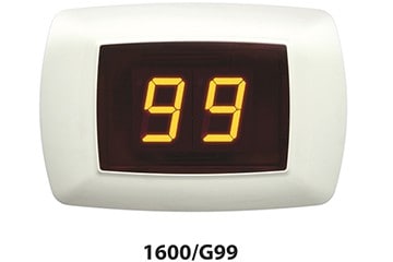
12V AC – 5W
mm 123,5 x 84,0 – P = 37,0 mm
Box = 1 pz
Large G99 display – wall mounted
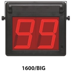
12V AC
mm 278,0 x 240,0 – P = 74,0 mm
Box = 1 pz
– Height of digits = 135 mm
– Angle of view = 150°
– Power supply = 12V AC – 6W
– Dimensions = 275x240x55mm
– Weight = 1kg – abs cabinet
Max. 99 calls, optical and acoustical alarm, automatic assignment of numbers to calling rooms, serial connection with 4 wires.
Room interface for G99
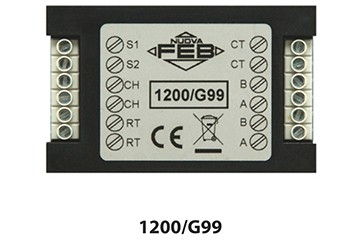
12V AC
mm 80,0 x 51,0 – P = 23,0 mm
Box = 1 pz
– Power supply = 12V AC
– Power absorption = 1W max
– Dimensions = 80x50x20 mm
– Signal transmission delay = 0,02 sec
Signal delay calculation
Wires size
– Power supply: the section can be calculated with the practical formula S = N x 0.015, where S is the section in mm² and N is the number of room interfaces. Example: 50 rooms system S = 50 x 0,015 = 0,75mm².
General reset unit for G99
12V AC
mm 80,0 x 51,0 – P = 23,0 mm
Box = 1 pz
– Power supply = 12V AC
– Power absorption = 1W max
– Dimensions = 80x50x20 mm
– Signal transmission delay = 0,02 sec
PC interface for the G99 system
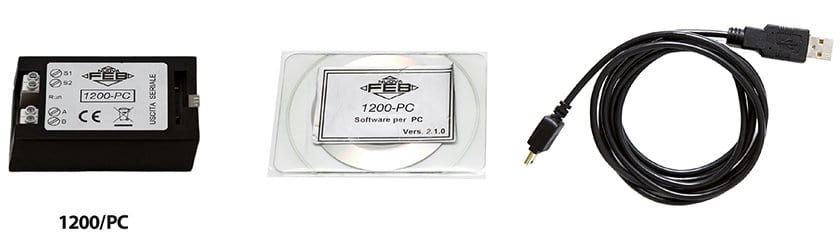
12V AC – 1W
mm 80,0 x 51,0 – P = 23,0 mm
Box = 1 pz
It displays on a PC monitor the calls coming from the 1600/G99 unit.
– Free text description of incoming calls.
– USB connection.
– Software supplied on a CD.
– Requires Windows 98, 2000, XP.
– Dimensions 80x50x20mm (for junction box).
Interface to drive additional signaling devices for G99 units
12V AC – 1W
mm 80,0 x 51,0 – P = 23,0 mm
Box = 1 pz
– Max current 2A
– Power supply 12VAC 1W
– Dimensions 85x50x20mm (for junction box).
DIN rail/wall mount transformer for G99 – 4 DIN
230V/12V AC – 63VA 50/60Hz
mm 72,0 x 115,0 – P = 61,0 mm
Box = 1 pz
Transformer to supply power to the G99 system
– The power absorbed by the system, given in VA, is calculated by the practical formula P=Nx2, where N is the number of room interfaces. Example: system with 50 rooms P=50×2=100VA.
If necessary, it is possible to connect in parallel more than one transformer, provided that care is paid to realize a correct connection.
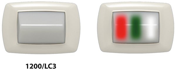
1200/LC3 – ACOUSTICAL/OPTICAL SIGNALING DEVICE WITH ROOM INTERFACE FOR G99
Working Principle:
Room call button: it sends the alarm to the main system and turns on the RED LED which indicates the calling room.
Bathroom call button: it sends the alarm to the main system and turns on the WHITE LED which indicates the calling room.
Reset button: 1st push: it resets the calling device, turns off the RED or WHITE LED and turns on the GREEN LED which indicates that the nurse is in the room.
Reset button: 2nd push: it turns off the GREEN LED and resets the calling system.
The call button is always active.
The reset button is activated only after the call button has been pushed.
The device is designed according to the DIN VDE 0834-1 norm
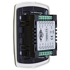
12V AC
Can be installed inside a 503 wall box
Box = 1 pz
Technical Specs:
– Power supply: 12VAC – by a safety transformer.
– Max consumption: 2W
– Light signal: High brightness red, green and white LEDs.
– Sound signal: 1 piezo buzzer rated at 60dB at 1 meter.
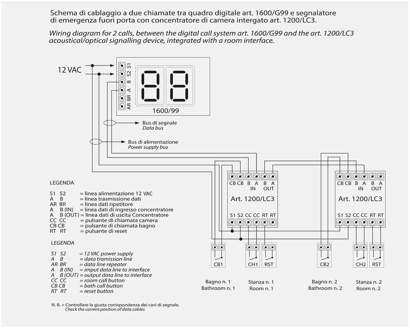
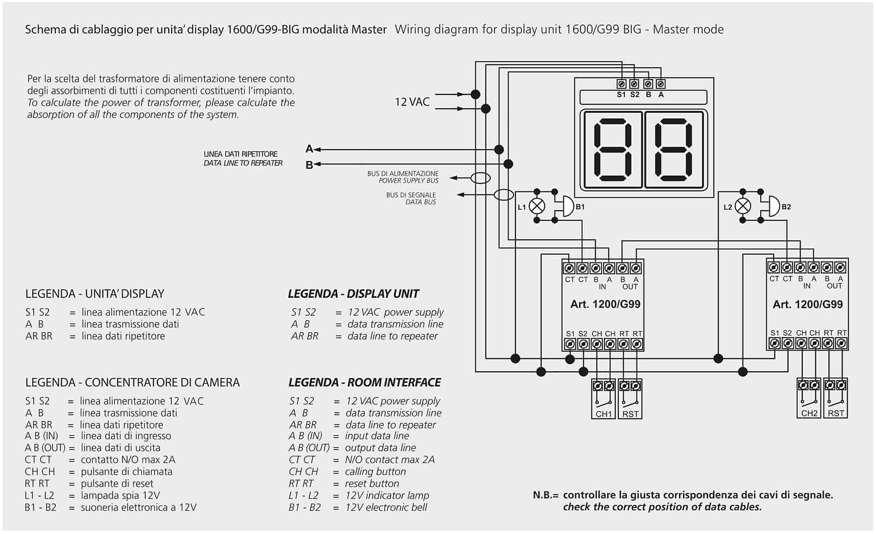
G99 SYSTEM – CONNECTION DIAGRAMS
Wiring diagram for display unit 1600/G99 or 1600/BIG – Master mode
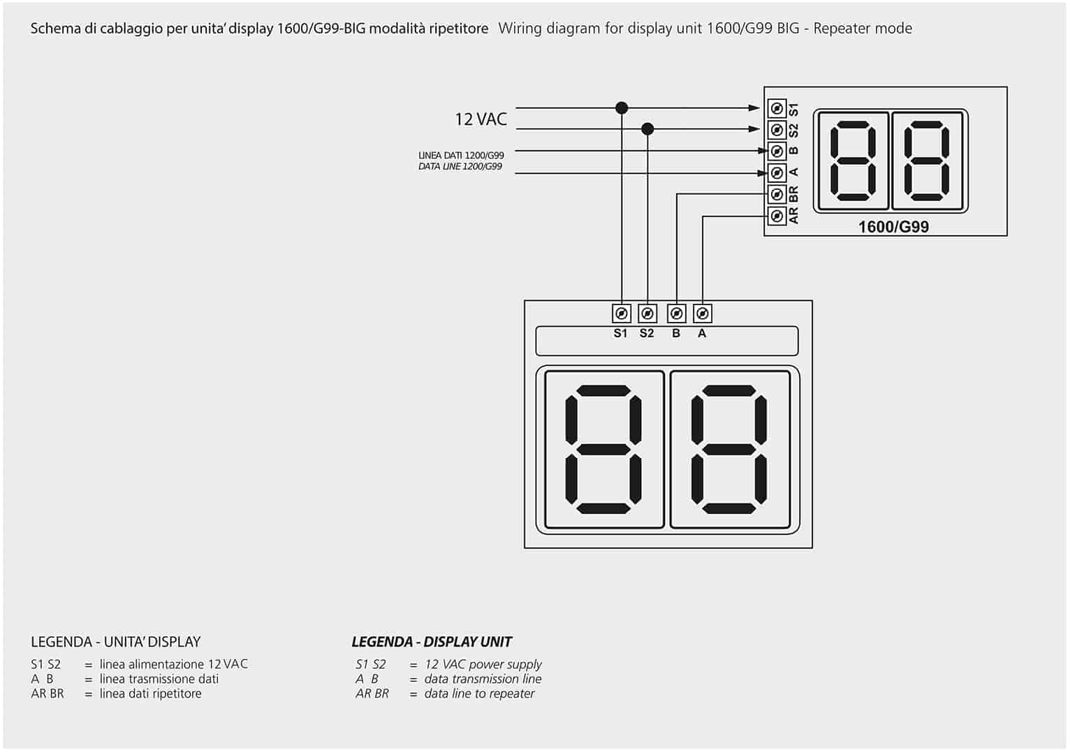
Wiring diagram for display unit 1600/G99 or 1600/BIG – Repeater mode
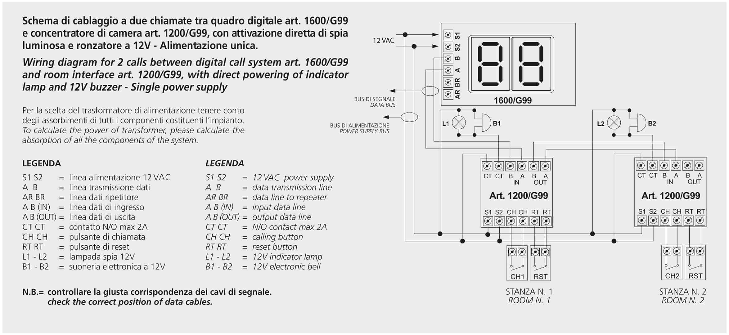
Wiring diagram for 2 calls between digital call system 1600/G99 or 1600/BIG and the room interface P/N 1200/G99, with direct powering of an indicator lamp and a 12V buzzer – Single power supply
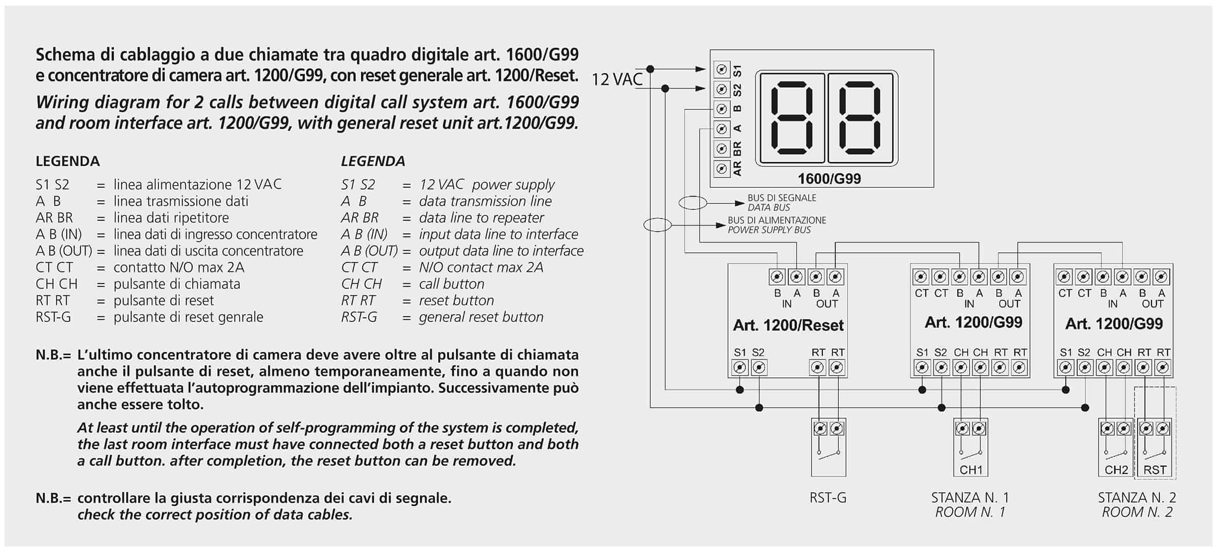
Wiring diagram for 2 calls between digital call system 1600/G99 or 1600/BIG and the room interface P/N 1200/G99, with the general reset unit 1200/RESET
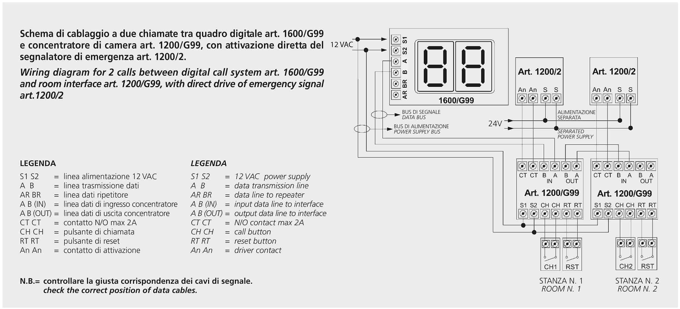
Wiring diagram for 2 calls between digital call system 1600/G99 or 1600/BIG and the room interface P/N 1200/G99, with direct drive of the emergency signal 1200/2